LTE-A and LTE architecture has utilized the real power of the Mobility.
With LTE download of upto 100Mbps and upload of 50mbps on a Mobile device.
In LTE-Advanced focus is on higher capacity:The driving force to further develop LTE towards LTE–Advanced - LTE Release10 was to provide higher bitrates in a cost efficient way and, at the same time, completely fulfil the requirements set by ITU for IMT Advanced, also referred to as 4G.
- Increased peak data rate, DL 3 Gbps, UL 1.5 Gbps
- Higher spectral efficiency, from a maximum of 16bps/Hz in R8 to 30 bps/Hz in R10
- Increased number of simultaneously active subscribers
- Improved performance at cell edges, e.g. for DL 2x2 MIMO at least 2.40 bps/Hz/cell.
Carrier Aggregation
The most straightforward way to increase capacity is to add more bandwidth. Since it is important to keep backward compatibility with R8 and R9 mobiles the increase in bandwidth in LTE-Advanced is provided through aggregation of R8/R9 carriers. Carrier aggregation can be used for both FDD and TDD.Each aggregated carrier is referred to as a component carrier. The component carrier can have a bandwidth of 1.4, 3, 5, 10, 15 or 20 MHz and a maximum of five component carriers can be aggregated. Hence the maximum bandwidth is 100 MHz. The number of aggregated carriers can be different in DL and UL, however the number of UL component carriers is never larger than the number of DL component carriers. The individual component carriers can also be of different bandwidths, see figure 1.

| Figure 1. Carrier Aggregation – FDDThe R10 UE can be allocated resources DL and UL on up to five Component Carriers (CC). The R8/R9 UEs can be allocated resources on any ONE of the CCs. The CCs can be of different bandwidths. |
|---|
The easiest way to arrange aggregation is to use contiguous component carriers within the same operating frequency band (as defined for LTE), so called intra-band contiguous. This might not always be possible, due to frequency allocation scenarios. For non-contiguous allocation it could either be intra-band, i.e. the component carriers belong to the same operating frequency band, but are separated by a frequency gap, or it could be inter-band, in which case the component carriers belong to different operating frequency bands, see figure 2.
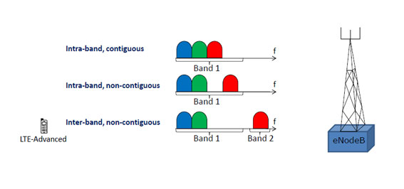
| Figure 2 Carrier Aggregation – Intra- and inter-band alternatives. |
|---|
In the inter-band CA example shown in figure 3, carrier aggregation on all three component carriers is only possible for the black UE, the white UE is not within the coverage area of the red component carrier.

| Figure 3. Carrier Aggregation; Serving CellsEach Component Carrier corresponds to a serving cell. The different serving cella may have different coverage. |
|---|
MIMO, Multiple Input Multiple Output – or spatial multiplexing
MIMO is used to increase the overall bitrate through transmission of two (or more) different data streams on two (or more) different antennas - using the same resources in both frequency and time, separated only through use of different reference signals - to be received by two or more antennas, see figure 4.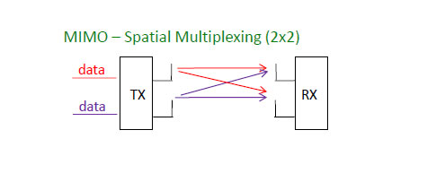
| Figure 4. Simplified illustration of 2x2 MIMO (Spatial Multiplexing). Two different data streams are transmitted on two TX antennas and received by two RX antennas, using the same frequency and time, separated only by the use of different reference signals. |
|---|
MIMO can be used when S/N (Signal to Noise ratio) is high, i.e. high quality radio channel. For situations with low S/N it is better to use other types of multi-antenna techniques to instead improve the S/N, e.g. by means of TX-diversity, see figure 5.
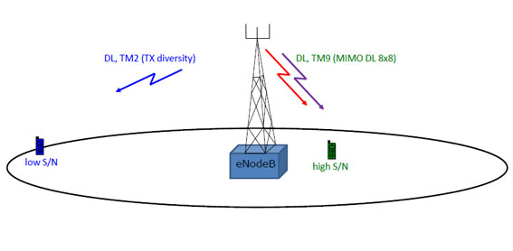
| Figure 5. MIMO is recommended for high S/N and TX diversity is preferably used for low S/N scenarios. |
|---|
- Number of layers (streams, or rank)
- Antenna ports used
- Type of reference signal, Cell-specific Reference Signal (CRS) or Demodulation Reference Signal (DM-RS), introduced in R10.
- Precoding type
In multi-antenna techniques precoding is used to map the modulation symbols onto the different antennas. The type of precoding depends on the multi-antenna technique used as well as on the number of layers and the number of antenna ports. The aim with precoding is to achieve the best possible data reception at the receiver.
Note that the signal will be influenced by fading of various types, which can also be seen as some type of coding caused by the radio channel.To handle this, known reference signals will be transmitted together with the data, and used by the receiver for demodulation of the received signal.
In R8 the reference signal is added to the signal after precoding, one CRS (Cell-specific Reference Signal) per antenna. From the received CRS the UE estimates how the radio channel influenced the signal. Using this together with knowledge about the used code-book based precoding, the UE can demodulate the received signal and regenerate the information sent.
In R10 the DM-RSs (Demodulation Reference Signals) are added to the different data streams before precoding. Knowledge about the reference signal will provide information about the combined influence of radio channel and precoding, no pre-knowledge about the precoder is required by the receiver, this case is referred to as non-codebook based precoding, see figure 6.
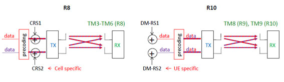
| Figure 6. MIMO DL with precoding and reference signal for demodulation in R8 and R10. CRS is a cell specific reference signal, DM-RS is a UE specific reference signal, also specific per data stream. |
|---|
Relay Nodes
In LTE-Advanced, the possibility for efficient heterogeneous network planning – i.e. a mix of large and small cells - is increased by introduction of Relay Nodes (RNs). The Relay Nodes are low power base stations that will provide enhanced coverage and capacity at cell edges, and hot-spot areas and it can also be used to connect to remote areas without fibre connection. The Relay Node is connected to the Donor eNB (DeNB) via a radio interface, Un, which is a modification of the E-UTRAN air interface Uu. Hence in the Donor cell the radio resources are shared between UEs served directly by the DeNB and the Relay Nodes. When the Uu and Un use different frequencies the Relay Node is referred to as a Type 1a RN, for Type 1 RN Uu and Un utilize the same frequencies, see figure 7. In the latter case there is a high risk for self interference in the Relay Node, when receiving on Uu and transmitting on Un at the same time (or vice versa). This can be avoided through time sharing between Uu and Un, or having different locations of the transmitter and receiver. The RN will to a large extent support the same functionalities as the eNB – however the DeNB will be responsible for MME selection.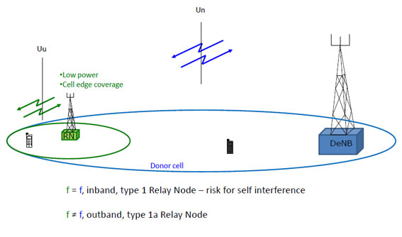
| Figure 7. The Relay Node (RN) is connected to the DeNB via the radio interface Un. UEs at the edge of the donor cell are connected to the RN via Uu, while UEs closer to the DeNB are directly connected to the DeNB via the Uu interface. The frequencies used on Un and Uu can be different, outband, or the same, inband. In the inband case there is a risk for self interference in the RN. |
|---|
Coordinated Multi Point operation (CoMP) – R11
LTE-Advanced continues to evolve. New CA configurations are added (additions of new bands for CA are not bound to specific releases) and there are new features introduced in coming releases of the 3GPP specifications, such as Coordinated Multi Point (CoMP) introduced in R11.The main reason to introduce CoMP is to improve network performance at cell edges. In CoMP a number of TX (transmit) points provide coordinated transmission in the DL, and a number of RX (receive) points provide coordinated reception in the UL. A TX/RX-point constitutes of a set of co-located TX/RX antennas providing coverage in the same sector. The set of TX/RX-points used in CoMP can either be at different locations, or co-sited but providing coverage in different sectors, they can also belong to the same or different eNBs. CoMP can be done in a number of ways, and the coordination can be done for both homogenous networks as well as heterogeneous networks. In figure 8 two simplified examples for DL CoMP is shown. In both these cases DL data is available for transmission from two TX-points. When two, or more, TX-points, transmit on the same frequency in the same subframe it is called Joint Transmission. When data is available for transmission at two or more TX-points but only scheduled from one TX-point in each subframe it is called Dynamic Point Selection. For UL CoMP there is for example Joint Reception, a number of RX-points receive the UL data from one UE, and the received data is combined to improve the quality. When the TX/RX-points are controlled by different eNBs extra delay might be added, since the eNBs must communicate, for example in order to make scheduling decisions. When CoMP is used additional radio resources for signaling is required e.g. to provide UE scheduling information for the different DL/UL resources.
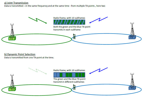
| Figure 8. DL CoMP a) Joint Transmission; two TX-points transmit to one UE in the same radio resource, b) Dynamic Point Selection; two TX points are ready to transmit, but only one will be scheduled in each subframe. |
Further reading
- TR 36.806 Evolved Universal Terrestrial Radio Access (E-UTRA); Relay architectures for E-UTRA (LTE-Advanced)
- TR 36.808 Evolved Universal Terrestrial Radio Access (E-UTRA); Carrier Aggregation; Base Station (BS) radio transmission and reception
- TR 36.814 Evolved Universal Terrestrial Radio Access (E-UTRA); Further advancements for E-UTRA physical layer aspects
- TR 36.815 Further Advancements for E-UTRA; LTE-Advanced feasibility studies in RAN WG4
- TR 36.817 Evolved Universal Terrestrial Radio Access (E-UTRA); Uplink multiple antenna transmission; Base Station (BS) radio transmission and reception
- TR 36.819 Coordinated multi-point operation for LTE physical layer aspects
- TR 36.823 Evolved Universal Terrestrial Radio Access (E-UTRA); Carrier Aggregation Enhancements; UE and BS radio transmission and reception
- TR 36.826 Evolved Universal Terrestrial Radio Access (E-UTRA); Relay radio transmission and reception
- TR 36.871 Evolved Universal Terrestrial Radio Access (E-UTRA); Downlink Multiple Input Multiple Output (MIMO) enhancement for LTE-Advanced
- TR 36.912 Feasibility study for Further Advancements for E-UTRA (LTE-Advanced)
- TR 36.913 Requirements for further advancements for Evolved Universal Terrestrial Radio Access (E-UTRA) (LTE-Advanced)
- TS 36.101 Evolved Universal Terrestrial Radio Access (E-UTRA); User Equipment (UE) radio transmission and reception
- TS 36.211 Evolved Universal Terrestrial Radio Access (E-UTRA); Physical channels and modulation
- TS 36.212 Evolved Universal Terrestrial Radio Access (E-UTRA); Multiplexing and channel coding
- TS 36.213 Evolved Universal Terrestrial Radio Access (E-UTRA); Physical layer procedures
- TS 36.216 Evolved Universal Terrestrial Radio Access (E-UTRA); Physical layer for relaying operation
- TS 36.221 Evolved Universal Terrestrial Radio Access (E-UTRA); Medium Access Control (MAC) protocol specification
- TS 36.300 Evolved Universal Terrestrial Radio Access (E-UTRA) and Evolved Universal Terrestrial Radio Access Network (E-UTRAN); Overall description; Stage 2
- TS 36.306 Evolved Universal Terrestrial Radio Access (E-UTRA); User Equipment (UE) radio access capabilities
- TS 36.331 Evolved Universal Terrestrial Radio Access (E-UTRA); Radio resource Control (RRC) protocol specification
No comments:
Post a Comment